HFM Marine Heat Exchanger for Optimal Marine Applications
Boats function as isolated environments with limited resources, consisting of salty sea air to breathe, treated seawater to drink, and a confined living space. This is all part of the responsibility of ensuring a secure return.
At HFM, we recognize these unique hardships and offer a range of reliable and efficient thermal systems for vessels, featuring a diverse selection of marine heat exchanger. Our state-of-the-art devices are meticulously crafted to ensure peak performance for various closed-circuit cooling systems at sea, including marine oil cooler heat exchangers, marine engine heat exchanger, water cooling systems in ships, and HVAC applications. Contact Us or send us an email at: [email protected] to learn more.
Introduction of Plate Heat Exchangers in Marine Turbine
The significance of heat exchange in maintaining the regular operation of marine turbines cannot be understated, as these engines require precise temperature control for optimal functionality. Heat exchangers play a pivotal role in marine engines, encompassing main and auxiliary oil coolers, cylinder liners, freshwater coolers, fuel heaters, steam condensers, water heaters, and other essential equipment.
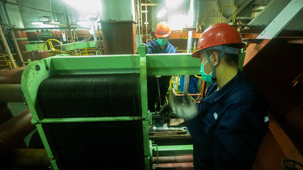
Seawater heat exchangers, including plate heat exchangers, are among the most critical types of equipment used in marine engines due to the unique working environment of ships. Vibration, shock, large-angle tilt, noise, high salt concentration, high humidity, and extreme plate corrosion are all factors that pose exceptional demands on heat exchangers.
Furthermore, the limited space and stringent quality requirements of marine structures make it difficult to accommodate heat exchangers. Traditional heat exchangers use water as the heat transfer medium, while marine heat exchangers typically use oil and water. The plate heat exchanger has emerged as a practical solution to many of these issues and is expected to become more prevalent in marine vessels in the future, especially as a marine heat exchanger.
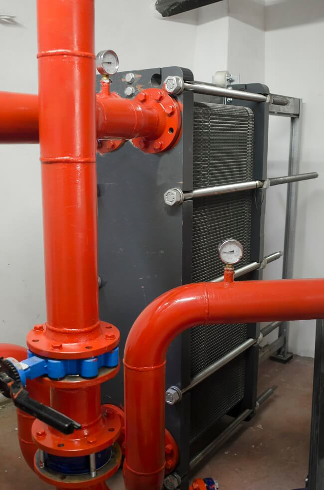
Compact and Reliable: The Advantages of Plate Heat Exchangers for Marine Heat Transfer
1. Compact and Lightweight Equipment for Vessels
In marine turbine systems, the use of plate heat exchangers has gained popularity due to their compact size and volume. To ensure maximum efficiency in a limited space, finite element analysis is employed to eliminate unnecessary parts of the plate and reduce weak points by locally thickening them according to the actual stress and strain distribution.
The use of gas cutting methods is applied to reduce the impact of welding deformation on the strength of the heat exchanger. The inner plate and panel are welded together to eliminate residual stress. These measures allow optimal use of the equipment in a limited space, ensuring reliable heat transfer and operation of the marine turbine system. Our marine heat exchangers, including heat exchanger marine and marine engine heat exchanger, offer compact and lightweight solutions tailored to vessel requirements.
2. Enhancing Equipment Stability for Optimal Heat Exchange in Marine Heat Exchangers
To ensure the stability of marine heat exchangers or seawater heat exchangers, a multi-point fixed method is employed to fix all selected parts and a rib structure is used to increase the stability of critical parts. The enhanced installation stability leads to optimized heat exchange efficiency and effectiveness of the plate heat exchanger, as problems such as vibration can otherwise negatively impact the heat transfer process.
3. Corrosion Resistance and Quality Assurance for Seawater Cooling in Turbines
Due to the direct contact of many turbines with seawater during operation, the heat transfer medium is significantly impacted. As a result, high corrosion-resistant materials, such as titanium, are frequently used for the plate in the turbine, despite its lower quality compared to stainless steel. Thorough 100% color penetration tests during routine inspections maintain the quality of our marine oil cooler heat exchanger and marine engine heat exchanger.
4. Improving Heat Transfer Efficiency with Oil-Water Heat Exchange
Due to the notable difference in specific heat capacity between water and oil, there is a significant temperature disparity that occurs during the heat transfer process. This translates to a more efficient heat transfer coefficient. To ensure the reliability and cost-effectiveness of the product, it is imperative to maintain optimal oil-water heat transfer performance under marine working conditions and to ensure that there is a specific heat exchange margin. Effective heat conduction by the heat medium is necessary to achieve optimal heat transfer efficiency.
5. Low Price and Operability
Plate heat exchangers are a cost-effective and widely-used option for marine heat transfer applications, particularly in seawater heat exchangers. With a mature production process, maintenance and cleaning can be performed with ease and at a lower cost compared to other types of heat exchangers. These compact and efficient devices can be quickly replaced in case of damage, and their low price makes them a practical choice for ensuring smooth operations, emergency equipment on vessels and contributing to a sustainable marine industry.
A faulty plate heat exchanger can lead to over 60% of energy wastage.
Empowering over 1300 clients, let us elevate the efficiency of your marine PHE!
The Role of Water Cooling System
The operation of diesel engine power results in the production of heat in some mechanical equipment. This heat must be distributed in a timely manner; otherwise, the temperature of the heating element will continue to rise beyond the allowable limits, which could compromise the reliability of the mechanical equipment.
To distribute this heat, a certain amount of liquid must continuously flow through the heat sink to bring the heat out of the equipment. Cooling systems commonly use freshwater, seawater, or river water as a cooling medium.
A significant portion of the heat removed by the cooling system is the residual heat generated by the fuel combustion, which typically accounts for around 20% to 30%. As a heat engine, the diesel engine relies on fuel combustion to generate heat to function, making it critical to effectively manage the dissipation of heat. Increasing the intensity of cooling can result in greater loss of this heat, leading to a reduction in diesel engine efficiency.
Additionally, due to the high temperature of the heat-receiving components, such as the inner wall of the cylinder which can reach temperatures of 200°C to 300°C, and the lower surface temperature in contact with the cooling water, there is a risk of thermal stress due to the temperature difference. Such a significant temperature difference can cause cracking of the component, highlighting the need for efficient cooling systems, including the use of marine heat exchangers, seawater heat exchangers, or plate heat exchangers.
It is apparent that the cooling process for diesel engines has stringent requirements. The primary objective of the cooling system is to reduce the heat generated by the diesel engine and maintain the temperature of each heated component within acceptable limits. This is accomplished by regulating the temperature of the cooling water and selecting an appropriate cooling medium, such as a marine heat exchanger, seawater heat exchanger or plate heat exchanger, to guarantee the engine’s consistent and dependable operation.
Therefore, when determining the appropriate cooling water temperature for a diesel engine, it is crucial to consider both insufficient and excessive cooling. Inadequate cooling can result in overheating, causing a decrease in material mechanical properties, thermal stress, deformation, increased surface gap, excessive wear, and damage to the engine. Additionally, it can lead to high oil temperatures, reduced oil lifespan, oil deterioration, coking, and loss of lubrication.
Conversely, excessive cooling can cause the coolant to absorb too much heat, leading to a reduction in diesel engine efficiency. Moreover, when using high-sulfur oil, excessive cooling can cause sulfuric acid formation, corroding the cylinder wall and piston. Therefore, it is essential to perform thermal equilibrium calculations for the cooling water system, taking into account marine heat exchangers, seawater heat exchangers, or plate heat exchangers to ensure the engine operates reliably and efficiently.
When operating a diesel power plant on a ship, it is essential to have cooling machinery and equipment to ensure efficient and reliable operation. These include:
- The main and auxiliary diesel engines, which consist of cylinders, pistons, injectors, and superchargers.
- Main and auxiliary diesel engine oil cooler and freshwater cooler
- Shaft bearings
- Air compressors and condensers
- Air conditioning and refrigeration units, deck machinery, hydraulic systems, and other marine heat exchangers.
Of all these machineries and equipment, the main engine requires the most significant amount of heat dissipation. To achieve this, the ship’s cooling system typically consists of a main cooling pipe as the center, with other machinery and equipment cooling pipes and a range of cooling auxiliary equipment working together.
The Basic Form of Water Cooling System
1. Open Water Cooling System
The open cooling water system involves using outboard water or river water to directly cool the diesel engine. While this system is easy to manage and maintain, it has its drawbacks. For example, the quality of outboard water is often poor, containing impurities and chlorinated salts. Those substances can block the cooling space, corrode parts, and reduce thermal efficiency due to scaling.
To avoid salt precipitation, the seawater temperature should be kept below 50-55 ℃, which means high-temperature components cannot be used. Since the diesel engine cooling water temperature is generally above 60 ℃, and high-speed machines require temperatures of 80 ℃ to 90 ℃, the open system is no longer applied except for riverboats.

2. Closed Water Cooling System
With regards to the open system, the closed cooling water system operates by utilizing fresh water to cool the diesel engine, while the heat exchanger cools the fresh water using outboard water. This signifies that the fresh water in the system undergoes a closed cycle, and the cooling of the fresh water occurs via an open cooling system that is distinct from the diesel engine’s cooling process. Consequently, this setup presents numerous advantages:
- The circulated water within the machine remains clean and fresh, which reduces the likelihood of blockages.
- Since clean water is utilized, fouling is avoided, which ensures efficient heat transfer and prolongs component lifespan.
- The system is not constrained by the temperature limits caused by salt precipitation in seawater, enabling the use of higher cooling water temperatures that improve thermal efficiency.
- The warm-up time for the cylinder is shortened, enhancing mobility. The fresh water bypasses the cooler or the closed seawater system once the tank has warmed up.
3. Central Water Cooling System
The diesel freshwater cooling system comprises of distinct circuits for high and low-temperature water. When high and low-temperature water system parameters are integrated, it constitutes a mixed-flow central cooling system; however, when the high and low-temperature circuits are separate, it becomes an independent central cooling system.
In an independent central cooling system, the use of low-temperature water freshwater to cool high-temperature water heat exchanger denotes the independent type I, whereas employing seawater to cool high-temperature water is referred to as the independent type II.
In high-speed vessels, such as container ships, the central cooler’s low-temperature fresh water cooler, commonly known as a bucket cooler, can be configured to cool the seawater acquired by the ship’s speed, which is designated as the self-flow central cooling system. This form of cooling system is a specific type of independent type I.
The Principle of Water Cooling System
The cooling water system in ship and marine vessel can be classified into two main categories, namely the seawater cooling system and the freshwater cooling system, which can be further subdivided into low-temperature and high-temperature water cooling systems, the latter being also referred to as the cylinder water cooling system.
A typical approach utilized by large-scale vessels is the employment of a centralized water cooling system, which can be a combination of these systems, commonly referred to as the water cooling system. In this context, we present an overview of the traditional seawater cooling system and the self-contained centralized water cooling system.
Conventional Seawater Cooling System
The typical method for cooling seawater involves several components including two pumps for seawater, oil coolers, cylinder water coolers, temperature control valves, return lines, and other elements. The process operates through the seawater pumps drawing in seawater from the seawater gate and pipes. The seawater is then directed in two ways: one path goes to the host air cooler, while the other is sent to the oil cooler. Afterward, the freshwater cooler combines with the discharged water from the host air cooler, flows through the three-way thermostat, and is either directed outward or returned to the seawater pump inlet.
The temperature of seawater is constantly changing due to factors such as seasonal changes or differences in sailing areas. To maintain the temperature of the seawater within an acceptable range, a three-way thermostatic valve is installed on the pipeline of seawater discharge. This valve allows the seawater to be returned to the inlet when its temperature falls below the desired level. The temperature sensor on the outlet pipe of the seawater pump controls the opening and closing of the valve.
Most ships have at least two seawater doors, positioned low and on both sides of the vessel. In addition, some ships have a high seawater door to prevent sediment inhalation while sailing in shallow waters. However, for safety purposes, larger ships are typically equipped with three seawater doors, including one high seawater door and two low seawater doors.
It is essential to cool the lubricating oil first before cooling the freshwater using the freshwater cooler. This is because the oil temperature is lower than that of freshwater, and its viscosity is higher, making it less effective at heat exchange than freshwater. By cooling the lubricating oil first, the overall efficiency of the cooling system is improved, leading to reduced energy consumption.
Independent Central Water Cooling System Type Ⅰ
The independent type Ⅰ central cooling water system comprises three distinct circuits, namely the seawater circuit, the high-temperature freshwater circuit, and the low-temperature freshwater circuit, each operating autonomously.
1. Seawater Circuit
With regard to the seawater circuit, its configuration is relatively uncomplicated. It involves two seawater pumps that draw seawater from the seawater mains and transport it to the central cooler. The cool low-temperature freshwater is then discharged externally.
2. High-Temperature Freshwater Circuit
The high-temperature freshwater circuit, known as the host cylinder water cooling system, functions as a closed-loop system, whereby two high-temperature freshwater pumps propel high-temperature freshwater into the host cylinder for cooling the piston and injector, subsequently being discharged from the main engine’s highest point. The high-temperature freshwater then flows through the three-way thermostat valve, high-temperature freshwater cooler or bypass pipe, and gas cabinet before returning to the suction port of the high-temperature freshwater pump.
To maximize energy efficiency, a water machine or light system is installed parallel to the host freshwater discharge pipeline, utilizing the high-temperature freshwater waste heat to generate freshwater, which can be utilized as added fresh water on board.
In order to maintain the desired host freshwater outlet temperature of approximately 80 ℃, a three-way thermostat valve is installed in the inlet and outlet bypass line of the high-temperature freshwater cooler. While there are three different methods for adjusting the temperature of the freshwater in the main machine, adjusting the amount of low-temperature freshwater or seawater entering the high-temperature freshwater cooler is rarely used as it results in the host’s inlet and outlet water temperature being too large or too slow. The installation of a three-way thermostat valve in the inlet pipe and outlet pipe is recommended for optimal control.
The system also includes a high-temperature water expansion tank, which enables freshwater flowing in the closed circulation lines to expand and contract due to temperature changes while expelling vaporized gas out of the system through the highest point of freshwater exports connected to a ventilation pipe and expansion tank. The expansion tank also maintains high water pressure in the suction pipe to prevent low-pressure vaporization, stabilize pressure, and add freshwater loss. Water quality can be treated at the dosing sites.
The system also features a high-temperature water expansion tank, which can:
- The system allows for the volume changes due to temperature fluctuations by accommodating the expansion of freshwater flowing in closed circulation lines.
- The expulsion of vaporized gas caused by local heat in the pipeline is facilitated by the highest point of freshwater exports being connected to a ventilation pipe and an expansion tank.
- The static pressure head in the expansion tank can be utilized to maintain high water pressure in the suction pipe, preventing low-pressure vaporization in the pipe and maintaining pressure stability.
- The expansion tank can be used to compensate for any freshwater loss.
- Water quality in the dosing sites can be effectively managed.
3. Low-Temperature Freshwater Circuit
The cryogenic freshwater circuit is a closed-loop system that requires cooling by seawater. It is more complex than conventional seawater cooling systems and is divided into various ways for low-temperature water distribution. The system includes a three-way thermostatic valve installed in the central cooler outlet to control the outlet temperature at 36°C. Additionally, a special low-temperature water expansion tank is established, and two pumps are installed, one of which is a spare and starts automatically to make a conversion.
Compared to the independent Type I central cooling water system, the Type II system has a main cooler called the low-temperature freshwater cooler, which is also cooled by seawater. The main difference between the two arrangements is the position of the cooling pump and the cooler in the closed circulatory system, and how the freshwater pump is connected to the freshwater inlet line or the outlet line.
The freshwater pump first enters the main engine inlet, which can maintain high pressure to ensure good cooling of the diesel engine, but the pressure of the cooling water from the host entering the cooler is reduced, and seawater may leak into the freshwater at the cooler tube sheet. In the second arrangement, freshwater from the cooling pump first enters the freshwater cooler, then cools the host components, and finally returns to the cooling pump suction port. The advantages and disadvantages of this arrangement are the opposite of the first arrangement.
Learn More About HFM Marine Application